Social networks like Twitter, Facebook, Whatsapp, and others are run by companies.
When using these networks to stay in touch with friends
You have to trust the company with the content of your conversations.
Usually the companies mine the data and inject targeted advertising into your feed.
Secret algorithms are used to emphasize or de-emphasize information and one has to trust the company that it is not using these mechanisms to influence public opinion.
Nostr is an open protocol and a network of participating relays and clients.
In a similar fashion as Bitcoin, the network is distributed (i.e. there are multiple relays).
Accounts are just a pair of secret and public key. I.e. similar as with Bitcoin there is no registration using email and/or mobile phone number required.
Because users are not bound to a particular client (or relay), they can without effort switch clients and relays if the interface becomes cluttered with ads or if the quality of service is low in any other way.
Nostr even lets you add Bitcoin Lightning payment links to all of your post so viewers of your post can give you small tips if they like your content.
I have tested a few clients (for desktop and web) and at the moment in my opinion the web application iris.to is the best choice.
Now I am going to give you a non-technical guide on how to get started using this web application.
Using the Iris.to Nostr client web application
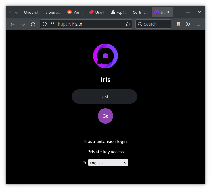
When opening the website the first time one is greeted with a login page.
The login page asks you for your display name and here I just entered test for demonstration purposes.
When clicking Go, the web application creates a public and private key pair.
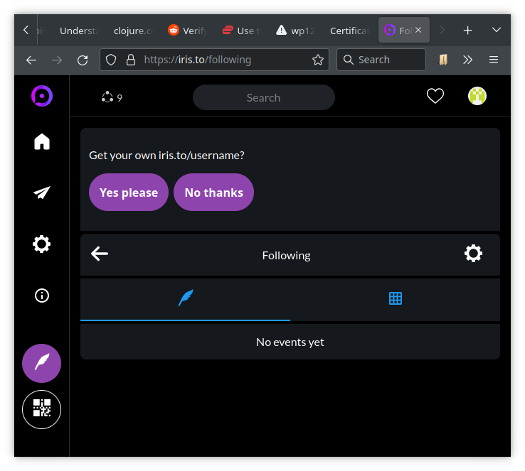
The next page shows you a selection of popular accounts which you can choose to add to your feed by pressing one or more of the Follow buttons.
The next page lets you choose a unique user name for the iris.to website.
If you for example choose testit, you get a human-readable Nostr address (a so called NIP-05 name) called testit@iris.to.
Of course you can always choose to get a new Nostr identity from another website.
If you have a private homepage with the URL https://myhomepage.org, you can even create your own Nostr identity testit@myhomepage.org.
More about this later.
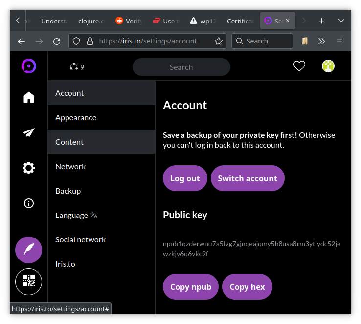
If you navigate to the account page, you will see your public key, which is a long string starting with npub....
If you scroll down, you will see a button to copy your private key to the clipboard.
The secret key is a long string starting with nsec....
Now is a good time to store this private key securely, otherwise you will permanently loose access to this account.
If you loose your secret key, your only option is to start over with a new account.
You will need this key if you get a new PC or if you want to use Nostr on another device or client.
Depending on your browser’s privacy settings, you might need the key next time you restart the browser.
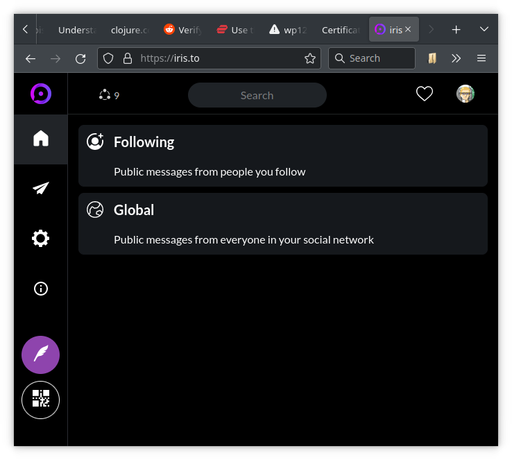
When clicking on the home icon, one gets presented with two options:
Following: show messages from accounts you follow
Global: show messages from your extended social network
When clicking on Following, you will see a real-time feed from accounts you follow.
Also the top of the page shows you a button to copy a link to your public feed to the clipboard.
If you haven’t chosen a human-readable Nostr identity, the link will be something like https://iris.to/npub....
If you have chosen the name testit, your public link will be https://iris.to/testit.
If you are using your private homepage to create a Nostr identity, you can also use https://iris.to/testit@myhomepage.org as public link.
BTW, if you are looking for new type of content, you can search using the hash-tag #grownostr.
BTW, if you want to send/receive zaps (small tips using Bitcoin Lightning), I can recommend the Alby web wallet.
Advanced Users
This section is for advanced users only and is purely optional.
Nostr extension login (somewhat advanced)
You might have noticed that in my screenshot the login page has a clickable Nostr extension login link which makes login easier.
This is because I am using the Firefox extension nos2x-fox which manages logging in without revealing the private key to the web application.
In my case if I go to the account page, there is no option to copy the private key because the web application does not know it.
In a similar fashion, desktop clients can post messages to relay servers without revealing the private key.
Nostr address using private homepage (more advanced)
Note that the account page also has a Copy hex button which lets you copy your public key in hexadecimal form.
In order to use your homepage to give you a check mark verifying the Nostr address testit@myhomepage.org, you need to place a JSON file at https://myhomepage.org/.well-known/nostr.json with the following content:
{"names":{"testit":"<your public hex key>"}}
Also you need to enable CORS.
You can do this by adding a .htaccess file with the following content in the .well-known folder:
Header set Access-Control-Allow-Origin "*"
Header set Access-Control-Allow-Methods "GET"
Header set Access-Control-Allow-Headers "Content-Type, Authorization"
In two dimensions curl noise is fairly easy to understand and implement.
For a thorough description of 2D curl noise see Keith Peters’ article “Curl noise, demystified”.
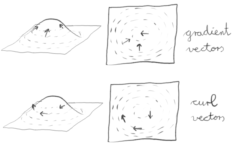
Basically one starts with a potential field such as multiple octaves of Worley noise.
One then extracts the 2D gradient vectors and rotates them by 90°.
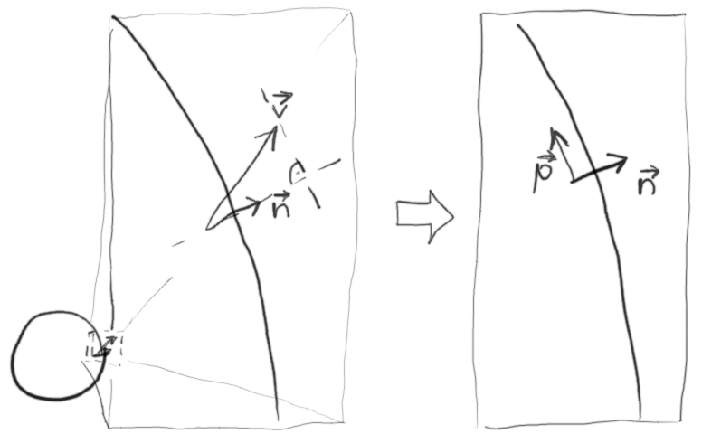
To generate curl vectors for a spherical surface one can use 3D Worley noise and sample the gradients on the surface of the sphere.
The gradient vectors then need to be projected onto the sphere.
This can be achieved by projecting the gradient vector onto the local normal vector of the sphere using vector projection.
By subtracting the projected vector from the gradient vector one obtains the tangential component of the gradient vector.
The resulting vector p needs to be rotated around the normal n by 90°.
This can be achieved by rotating the vector p into a TBN system, rotating by 90° around N and then transforming back.
The GLSL functions for the rotation (without OpenGL tests) are shown below:
#version 410 core
vec3orthogonal_vector(vec3n){vec3b;if(abs(n.x)<=abs(n.y)){if(abs(n.x)<=abs(n.z))b=vec3(1,0,0);elseb=vec3(0,0,1);}else{if(abs(n.y)<=abs(n.z))b=vec3(0,1,0);elseb=vec3(0,0,1);};returnnormalize(cross(n,b));}mat3oriented_matrix(vec3n){vec3o1=orthogonal_vector(n);vec3o2=cross(n,o1);returntranspose(mat3(n,o1,o2));}// note that axis needs to be a unit vectorvec3rotate_vector(vec3axis,vec3v,floatcos_angle,floatsin_angle){mat3orientation=oriented_matrix(axis);vec3oriented=orientation*v;mat2rotation=mat2(cos_angle,sin_angle,-sin_angle,cos_angle);vec3rotated=vec3(oriented.x,rotation*oriented.yz);returntranspose(orientation)*rotated;}
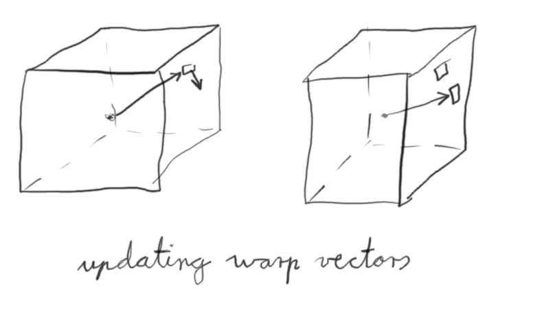
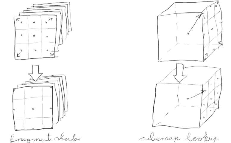
In OpenGL one can create a cubemap where each pixel on each surface contains a 3D warp vector.
Using a fragment shader the cubemap is initialised to be an identity transform for unit vectors.
A second fragment shader is used to initialise a cubemap with the curl vectors which are tangential to the sphere.
A third fragment shader is called multiple times to renormalize and increment the identity transform to become a warp field.
A final fragment shader uses the cubemap warp field to perform lookups in a 3D Worley noise field to generate a cubemap of the global cloud cover.
If one uses octaves of Worley noise one obtains vortices rotating in one direction.
To obtain prevailing winds and vortices with different direction of rotation depending on the latitude one can use the function (1+sin(2.5*latitude))/2 to mix positive and negative Worley noise.
Below is a result obtained using the method described in this article.
Another detail I forgot to mention is that the fragment shaders and the cubemap texture lookups use modified vectors to avoid performing lookups in the texture clamping regions which would lead to seams in the cloud cover.
I.e. when converting fragment coordinates, one increases the range of the index by half a pixel on both ends:
vec2x=(gl_FragCoord.xy-0.5)/(size-1);
Furthermore when performing lookups, two coordinates of the lookup vector are scaled down by half a pixel:
I have been playing with Chat GPT and I saw on Reddit that someone had the idea to ask it to write an ode to Clojure.
I tried it a few times as well and here is my favourite version:
Oh Clojure, a language so elegant and fine,
With your concision and power, you blow the mind.
Your Lisp roots run deep, and your functional core
Makes coding a joy, and never a bore.
Your homoiconicity is a thing of beauty,
Allowing code and data to flow with ease and duty.
Your interoperability with Java is a sight to see,
Allowing us to use the best of both worlds, merrily.
Your REPL is a treasure, allowing us to explore,
And test our code in a way that we adore.
Oh Clojure, you are a true work of art,
A language that is loved by many a heart.
Here’s to you, dear Clojure, may you continue to shine,
A beacon of simplicity, power, and design.
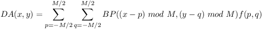
Initially a binary pattern BP is created where N pixels (about 10 percent) are set to 1 and the rest to 0.
The binary pattern then is convolved with the following filter function to generate the density array DA:
You can use a sigma value of 1.5.
The convolution is wrapped around to facilitate a tileable result:
Maxima of the density array are called clusters and minima are called voids.
The 1 value in BP with the highest density value DA (tightest cluster) is set to 0 and DA is updated accordingly.
Now the 0 value in BP with the lowest density value DA (largest void) is set to 1 (and DA is updated).
This is repeated until disolving the tightest cluster creates the largest void.
This is done to spread the 1 values evenly.
Phase 1
In phase 1 of the dithering algorithm the 1 values of a copy of the seed pattern are removed one by one starting where the density DA is the highest.
A copy of the density array DA is updated accordingly.
The corresponding positions in the resulting dither array are set to N-1, N-2, …, 0.
Phase 2
In phase 2 starting with the seed pattern a mask is filled with 1 values where the density DA is the lowest.
The density array DA is updated while filling in 1 values.
Phase 2 stops when half of the values in the mask are 1.
The corresponding positions in the dither array are set to N, N+1, …, (M * M) / 2 - 1
Phase 3
In phase 3 the density array DA is recomputed using the boolean negated mask from the previous phase (0 becomes 1 and 1 becomes 0).
Now the mask is filled with 1 values where the density DA is the highest (clusters of 0s) always updating DA.
Phase 3 stops when all the values in the mask are 1.
The corresponding positions in the dither array are set to (M * M) / 2, …, M * M - 1.
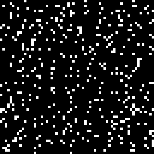
Result
The result can be normalised to 0 to 255 in order to inspect it.
The blue noise dither array looks as follows:
Here is an example with constant offsets when sampling 3D clouds without dithering.
Here is the same scene using dithering to set the sampling offsets.
One can apply a blur filter to reduce the noise.
Note how the blurred image shows more detail than the image with constant offsets even though the sampling rate is the same.
Let me know any comments/suggestions in the comments below.
Test driven development (TDD) undoubtedly helps a great deal in preventing development grinding to a halt once a project’s size surpasses a few lines of code.
The reason for first writing a failing test is to ensure that the test is actually failing and testing the next code change.
A minimal change to the code is performed to pass the new test while also still passing all previously written tests.
If necessary the code is refactored/simplified. The reason to do this after passing the test is so that one does not have to worry about passing the test and writing clean code at the same time.
Testing rendering output
One can test OpenGL programs by rendering test images and comparing them with a saved image (a test fixture).
In order to automate this, one can perform offscreen rendering and do a pixel-wise image comparison with the saved image.
Using the Clojure programming language and the Lightweight Java Game Library (LWJGL) one can perform offscreen rendering with a Pbuffer object using the following macro (of course this approach is not limited to Clojure and LWJGL):
(defnsetup-rendering"Common code for setting up rendering"[widthheight](GL11/glViewport00widthheight)(GL11/glEnableGL11/GL_DEPTH_TEST)(GL11/glEnableGL11/GL_CULL_FACE)(GL11/glCullFaceGL11/GL_BACK)(GL11/glDepthFuncGL11/GL_GEQUAL)(GL45/glClipControlGL20/GL_LOWER_LEFTGL45/GL_ZERO_TO_ONE))(defmacrooffscreen-render"Macro to use a pbuffer for offscreen rendering"[widthheight&body]`(let[pixels#(BufferUtils/createIntBuffer(*~width~height))pbuffer#(Pbuffer.~width~height(PixelFormat.2482400)nilnil)data#(int-array(*~width~height))](.makeCurrentpbuffer#)(setup-rendering~width~height)(try~@body(GL11/glReadPixels00~width~heightGL12/GL_BGRAGL11/GL_UNSIGNED_BYTEpixels#)(.getpixels#data#){:width~width:height~height:datadata#}(finally(.releaseContextpbuffer#)(.destroypbuffer#)))))
(defnis-image"Compare RGB components of image and ignore alpha values."[filename](fn[other](let[img(slurp-imagefilename)](and(=(:widthimg)(:widthother))(=(:heightimg)(:heightother))(=(map#(bit-and%0x00ffffff)(:dataimg))(map#(bit-and%0x00ffffff)(:dataother)))))))(defnslurp-image"Load an RGB image"[^Stringfile-name](let[img(.openImage(Opener.)file-name)](.convertToRGB(ImageConverter.img)){:width(.getWidthimg):height(.getHeightimg):data(.getPixels(.getProcessorimg))}))
The image is recorded initially by using the checker record-image instead of is-image and verifying the result manually.
(defnrecord-image"Use this test function to record the image the first time."[filename](fn[other](spit-imagefilenameother)))(defnspit-image"Save RGB image as PNG file"[^Stringfile-name{:keys[widthheightdata]}](let[processor(ColorProcessor.widthheightdata)img(ImagePlus.)](.setProcessorimgprocessor)(.saveAsPng(FileSaver.img)file-name)))
One can use this approach (and maybe only this approach) to test code for handling vertex array objects, textures, and for loading shaders.
Testing shader code
Above approach has the drawback that it can only test complete rendering programs.
Also the output is limited to 24-bit RGB images.
The tests are therefore more like integration tests and they are not suitable for unit testing shader functions.
However it is possible to use a Pbuffer just as a rendering context and perform rendering to a floating-point texture.
One can use a texture with a single pixel as a framebuffer.
A single pixel of a uniformly colored quad is drawn.
The floating point channels of the texture’s RGB pixel then can be compared with the expected value.
(defnshader-test[setupprobe&shaders](fn[uniformsargs](let[result(promise)](offscreen-render11(let[indices[0132]vertices[-1.0-1.00.5,1.0-1.00.5,-1.01.00.5,1.01.00.5]program(make-program:vertex[vertex-passthrough]:fragment(conjshaders(applyprobeargs)))vao(make-vertex-array-objectprogramindicesvertices[:point3])tex(texture-render11true(use-programprogram)(applysetupprogramuniforms)(render-quadsvao))img(texture->vectorstex11)](deliverresult(get-vectorimg00))(destroy-texturetex)(destroy-vertex-array-objectvao)(destroy-programprogram)))@result)))(defvertex-passthrough"#version 410 core
in highp vec3 point;
void main()
{
gl_Position = vec4(point, 1);
}")(defmacrotexture-render"Macro to render to a texture"[widthheightfloating-point&body]`(let[fbo#(GL45/glCreateFramebuffers)tex#(GL11/glGenTextures)](try(GL30/glBindFramebufferGL30/GL_FRAMEBUFFERfbo#)(GL11/glBindTextureGL11/GL_TEXTURE_2Dtex#)(GL42/glTexStorage2DGL11/GL_TEXTURE_2D1(if~floating-pointGL30/GL_RGB32FGL11/GL_RGBA8)~width~height)(GL32/glFramebufferTextureGL30/GL_FRAMEBUFFERGL30/GL_COLOR_ATTACHMENT0tex#0)(GL20/glDrawBuffers(make-int-buffer(int-array[GL30/GL_COLOR_ATTACHMENT0])))(GL11/glViewport00~width~height)~@body{:texturetex#:targetGL11/GL_TEXTURE_2D}(finally(GL30/glBindFramebufferGL30/GL_FRAMEBUFFER0)(GL30/glDeleteFramebuffersfbo#)))))(defntexture->vectors"Extract floating-point vectors from texture"[texturewidthheight](with-2d-texture(:texturetexture)(let[buf(BufferUtils/createFloatBuffer(*widthheight3))data(float-array(*widthheight3))](GL11/glGetTexImageGL11/GL_TEXTURE_2D0GL12/GL_BGRGL11/GL_FLOATbuf)(.getbufdata){:widthwidth:heightheight:datadata})))
Furthermore it is possible to compose the fragment shader by linking the shader function under test with a main function.
I.e. it is possible to link the shader function under test with a main function implemented just for probing the shader.
The shader-test function defines a test function using the probing shader and the shader under test.
The new test function then can be used using the Midje tabular environment.
In the following example the GLSL function phase is tested.
Note that parameters in the probing shaders are set using the weavejester/comb templating library.
(defphase-probe(template/fn[gmu]"#version 410 core
out lowp vec3 fragColor;
float phase(float g, float mu);
void main()
{
float result = phase(<%= g %>, <%= mu %>);
fragColor = vec3(result, 0, 0);
}"))(defphase-test(shader-test(fn[program])phase-probephase-function))(tabular"Shader function for scattering phase function"(fact(mget(phase-test[][?g?mu])0)=>(roughly?result))?g?mu?result00(/3(*16PI))01(/6(*16PI))0-1(/6(*16PI))0.50(/(*30.75)(*8PI2.25(pow1.251.5)))0.51(/(*60.75)(*8PI2.25(pow0.251.5))))
Note that using mget the red channel of the pixel is extracted.
Sometimes it might be more desirable to check all channels of the RGB pixel.
Here is the actual implementation of the tested function:
The empty function (fn [program]) is specified as a setup function.
In general the setup function is used to initialise uniforms used in the shader under test.
Here is an example of tests using uniform values:
(deftransmittance-track-probe(template/fn[pxpypzqxqyqz]"#version 410 core
out lowp vec3 fragColor;
vec3 transmittance_track(vec3 p, vec3 q);
void main()
{
vec3 p = vec3(<%= px %>, <%= py %>, <%= pz %>);
vec3 q = vec3(<%= qx %>, <%= qy %>, <%= qz %>);
fragColor = transmittance_track(p, q);
}"))(deftransmittance-track-test(transmittance-shader-test(fn[programheight-sizeelevation-sizeelevation-powerradiusmax-height](uniform-intprogram:height_sizeheight-size)(uniform-intprogram:elevation_sizeelevation-size)(uniform-floatprogram:elevation_powerelevation-power)(uniform-floatprogram:radiusradius)(uniform-floatprogram:max_heightmax-height))transmittance-track-probetransmittance-trackshaders/transmittance-forwardshaders/horizon-angleshaders/elevation-to-indexshaders/interpolate-2dshaders/convert-2d-indexshaders/is-above-horizon))(tabular"Shader function to compute transmittance between two points in the atmosphere"(fact(mget(transmittance-track-test[171716378000.0100000.0][?px?py?pz?qx?qy?qz])0)=>(roughly?result1e-6))?px?py?pz?qx?qy?qz?result00647800000647800010064280000064780000.50064530000064780000.75006428000006453000(/0.50.75))
Here a setup function initialising 5 uniform values is specified.
Mocking shader functions
If each shader function is implemented as a separate string (loaded from a separate file), one can easily link with mock functions when testing shaders.
Here is an example of a probing shader which also contains mocks to allow the shader to be unit tested in isolation:
Rhawk187 pointed out that exact image comparisons are also problematic because updates to graphics drivers can cause subtle changes. This can be adressed by allowing a small average difference between the expected and actual image.
The code of make-vertex-array-object and render-quads is added here for reference.
(defnmake-vertex-array-object"Create vertex array object and vertex buffer objects"[programindicesverticesattributes](let[vertex-array-object(GL30/glGenVertexArrays)](GL30/glBindVertexArrayvertex-array-object)(let[array-buffer(GL15/glGenBuffers)index-buffer(GL15/glGenBuffers)](GL15/glBindBufferGL15/GL_ARRAY_BUFFERarray-buffer)(GL15/glBufferDataGL15/GL_ARRAY_BUFFER(make-float-buffer(float-arrayvertices))GL15/GL_STATIC_DRAW)(GL15/glBindBufferGL15/GL_ELEMENT_ARRAY_BUFFERindex-buffer)(GL15/glBufferDataGL15/GL_ELEMENT_ARRAY_BUFFER(make-int-buffer(int-arrayindices))GL15/GL_STATIC_DRAW)(let[attribute-pairs(partition2attributes)sizes(mapsecondattribute-pairs)stride(apply+sizes)offsets(reductions+(cons0(butlastsizes)))](doseq[[i[attributesize]offset](maplist(range)attribute-pairsoffsets)](GL20/glVertexAttribPointer(GL20/glGetAttribLocation^intprogram(nameattribute))^intsizeGL11/GL_FLOATfalse^int(*strideFloat/BYTES)^int(*offsetFloat/BYTES))(GL20/glEnableVertexAttribArrayi)){:vertex-array-objectvertex-array-object:array-bufferarray-buffer:index-bufferindex-buffer:nrows(countindices):ncols(countattribute-pairs)}))))(defnrender-quads"Render one or more quads"[vertex-array-object](setup-vertex-array-objectvertex-array-object)(GL11/glDrawElementsGL11/GL_QUADS^int(:nrowsvertex-array-object)GL11/GL_UNSIGNED_INT0))