Note that LWJGL version 3 consists of several packages.
Furthermore most packages have native bindings for different platforms.
See LWJGL customization page for more information.
There is a Leiningen LWJGL project example by Roger Allen which shows how to install all LWJGL libraries using Leiningen.
However here we are going to use the more modern approach with a deps.edn file and we are going to use more efficient OpenGL indirect rendering.
The deps.edn file uses symbols of the form <groupID>/<artifactId>$<classifier> to specify libraries.
For LWJGL version 3 the classifier is used to install native extensions.
The deps.edn file for installing LWJGL with OpenGL and GLFW under GNU/Linux is as follows:
Displaying a window with GLFW instead of LWJGL 2 is a bit different.
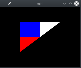
The updated code to use lwjgl-glfw and lwjgl-opengl to display a triangle with a small texture is shown below:
If you download the two files, you can run the code as follows:
clj -M raw-opengl-lwjgl3.clj
It should show a triangle like this:
Any feedback, comments, and suggestions are welcome.
This is a quick performance comparison of the Clojure core.matrix library and the Efficient Java Matrix Library.
Because core.matrix uses the VectorZ Java library as a backend, direct calls to VectorZ were also included in the comparison.
Finally I added fastmath to the comparison after it was pointed out to me by the developer.
The criterium 0.4.6 benchmark library was used to measure the performance of common matrix expressions.
The Clojure version was 1.11.1 and OpenJDK runtime version was 17.0.6.
Here are the results running it on an AMD Ryzen 7 4700U with a turbo speed of 4.1 GHz:
op
core. matrix 0.63.0
ejml-all 0.43
vectorz- clj 0.48.0
fastmath 2.2.1
make 4x4 matrix
675 ns
135 ns
50.5 ns
13.1 ns
make 4D vector
299 ns
47.6 ns
9.27 ns
3.67 ns
add 4D vectors
13.5 ns
18.2 ns
9.02 ns
4.29 ns
inverse matrix
439 ns
81.4 ns
440 ns
43.6 ns
elementwise matrix multiplication
64.9 ns
29.0 ns
29.1 ns
13.7 ns
matrix multi plication
102 ns
74.7 ns
100 ns
22.4 ns
matrix-vector multiplication
20.9 ns
31.2 ns
19.1 ns
6.46 ns
vector dot product
6.56 ns
6.90 ns
4.46 ns
6.36 ns
vector norm
10.1 ns
11.4 ns
no support?
3.74 ns
matrix determinant
170 ns
7.35 ns
166 ns
7.67 ns
matrix element access
4.14 ns
3.35 ns
3.26 ns
3.53 ns1
get raw data array
12.0 ns
3.00 ns
11.9 ns
13.2 ns1
1requires fastmath 2.2.2-SNAPSHOT or later
See matperf.clj for source code of benchmark script.
Comparing EJML with a mix of core.matrix and direct calls to vectorz:
EJML has support for both single and double precision floating point numbers
it uses single column matrices to represent vectors leading to slower matrix-vector multiplication
it has a fast 4x4 matrix inverse
it does not come with a Clojure wrapper
it offers fast access to raw data
it does not support multi-dimensional arrays
Comparing EJML with fastmath:
EJML has support for matrices larger than 4x4
EJML gives you access to the matrix as a flat floating point array (fastmath will add support in the future)
EJML is mostly slower
The implementations of the libraries are all quite impressive with custom optimisations for small matrices and vectors.
Note that I didn’t include Neanderthal in the comparison because it is more suitable for large matrices.
I hope you find this comparison useful.
Update:
The large performance difference for matrix inversion is probably because EJML has custom 4x4 matrix classes while VectorZ stops at 3x3.
Here is a performance comparison of matrix inverse for 3x3, 4x4, and 5x5 matrices:
Volumetric clouds use 3D density functions to represent clouds in a realistic way.
Ray marching is used to generate photorealistic rendering.
With modern graphics cards it is possible to do this in realtime.
Sebastian Lague’s video on cloud rendering shows how to generate Worley noise which can be used to generate realistic looking clouds.
Worley noise basically is a function which for each location returns the distance to the nearest point of a random set of points.
Usually the space is divided into cells with each cell containing one random point.
This improves the performance of determining the distance to the nearest point.
The following image shows a slice through inverted 3D Worley noise.
Ray marching works by starting a view ray for each render pixel and sampling the cloud volume which is a cube in this example.
This ray tracing program can be implemented in OpenGL by rendering a dummy background quad.
The transmittance for a small segment of the cloud is basically the exponent of negative density times step size:
The resulting sampled cube of Worley noise looks like this:
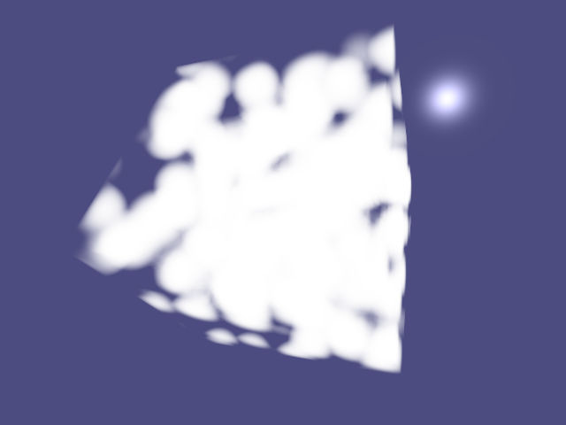
The amount of scattered light can be changed by using a mix of isotropic scattering and a phase function for approximating Mie scattering.
I.e. the amount of scattered light is computed as follows:
The resulting rendering of the Worley noise now shows a bright halo around the sun:
The rendering does not yet include self-shadowing.
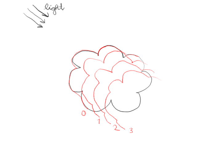
Shadows are usually computed by sampling light rays towards the light source for each sample of the view ray.
However a more efficient way is to use deep opacity maps (also see Pixar’s work on deep shadow maps).
In a similar fashion to shadow maps, a depth map of the start of the cloud is computed as seen from the light source.
While rendering the depth map, several samples of the opacity (or transmittance) behind the depth map are taken with a constant stepsize.
I.e. the opacity map consists of a depth (or offset) image and a 3D array of opacity (or transmittance) images.
Similar as when performing shadow mapping, one can perform lookups in the opacity map to determine the amount of shading at each sample in the cloud.
To make the cloud look more realistic, one can add multiple octaves of Worley noise with decreasing amplitude.
This is also sometimes called fractal Brownian motion.
To reduce sampling artifacts without loss of performance, one can use blue noise offsets for the sample positions when computing shadows as well as when creating the final rendering.
In a previous article I have demonstrated how to generate global cloud cover using curl noise.
One can add the global cloud cover with octaves of mixed Perlin and Worley noise and subtract a threshold.
Clamping the resulting value creates 2D cloud patterns on a spherical surface.
By restricting the clouds to be between a bottom and top height, one obtains prism-like objects as shown below:
Note that at this point it is recommended to use cascaded deep opacity maps instead of a single opacity map.
Like cascaded shadow maps, cascaded deep opacity maps are a series of cuboids covering different splits of the view frustum.
Guerilla Games uses a remapping function to introduce high frequency noise on the surfaces of the clouds.
The high frequency noise value is remapped using a range defined using the low frequency noise value.
An example obtained using these techniques is shown below:
The example was rendered with 28.5 frames per second.
an AMD Ryzen 7 4700U with passmark 2034 was used for rendering
the resolution of the render window was 640x480
3 deep opacity maps with one 512x512 offset layer a 7x512x512 transmittance array were rendered for each frame
5 octaves of 64x64x64 Worley noise were used for the high frequency detail of the clouds
a vertical profile texture with 10 values was used
3 octaves of 64x64x64 Perlin-Worley noise were used for the horizontal 2D shapes of the clouds
a 6x512x512 cubemap was used for the global cloud cover
Please let me know any suggestions and improvements!
Enjoy!
Update: I removed the clamping operation for the cover sample noise.
Update: Implementing the powder sugar effect is actually quite simple.
Essentially the increment to the scattered light by the cloud is multiplied with powder(density * stepsize) where the powder function is defined as follows:
The fact that there is less light to be scattered at the fringe of a cloud is approximated by reducing the amount of scattered light in low density areas of the cloud.
Update:
In order to reduce the blue noise, one can reduce the sampling interval.
Of course computing more samples requires more performance and reduces the frame rate of the implementation.
To address this problem, one can render the clouds to a low-resolution RGBA texture and then perform depth-aware upsampling.
Depth aware upsampling requires creating a low resolution distance buffer when rendering the clouds.
When rendering the scene at high resolution later, one then uses a shader for depth-aware bilinear upsampling as shown below.
The (high-resolution) depth of the current pixel is compared with the depth values of the low resolution texture.
Please read Bart Wronski’s article on bilinear downsampling and upsampling for more details about the bilinear downsampling and upsamling part itself.
#version 450 core
#define MAX_EXPONENT 20.0
uniformsampler2Dclouds;uniformsampler2Ddist;uniformintcloud_subsampling;uniformfloatdepth_sigma;uniformfloatmin_depth_exponent;uniformintoverlay_width;uniformintoverlay_height;constvec2vector01=vec2(0.0,1.0);vec4cloud_overlay(floatdepth){vec2point=gl_FragCoord.xy/cloud_subsampling;vec2texcoord=floor(point-0.5)+0.5;vec2frac=fract(point-0.5);vec2texcoord00=(texcoord+vector01.xx)/vec2(overlay_width,overlay_height);vec2texcoord01=(texcoord+vector01.yx)/vec2(overlay_width,overlay_height);vec2texcoord10=(texcoord+vector01.xy)/vec2(overlay_width,overlay_height);vec2texcoord11=(texcoord+vector01.yy)/vec2(overlay_width,overlay_height);vec4value00=texture(clouds,texcoord00);vec4value01=texture(clouds,texcoord01);vec4value10=texture(clouds,texcoord10);vec4value11=texture(clouds,texcoord11);floatdist00=texture(dist,texcoord00).r;floatdist01=texture(dist,texcoord01).r;floatdist10=texture(dist,texcoord10).r;floatdist11=texture(dist,texcoord11).r;floatexponent00=-(depth-dist00)*(depth-dist00)/(2*depth_sigma*depth_sigma);floatexponent01=-(depth-dist01)*(depth-dist01)/(2*depth_sigma*depth_sigma);floatexponent10=-(depth-dist10)*(depth-dist10)/(2*depth_sigma*depth_sigma);floatexponent11=-(depth-dist11)*(depth-dist11)/(2*depth_sigma*depth_sigma);// Need to guard against numerical underflows.floatweight00=(1.0-frac.x)*(1.0-frac.y)*exp(clamp(exponent00,min_depth_exponent,MAX_EXPONENT));floatweight01=frac.x*(1.0-frac.y)*exp(clamp(exponent01,min_depth_exponent,MAX_EXPONENT));floatweight10=(1.0-frac.x)*frac.y*exp(clamp(exponent10,min_depth_exponent,MAX_EXPONENT));floatweight11=frac.x*frac.y*exp(clamp(exponent11,min_depth_exponent,MAX_EXPONENT));return(value00*weight00+value01*weight01+value10*weight10+value11*weight11)/(weight00+weight01+weight10+weight11);}
Social networks like Twitter, Facebook, Whatsapp, and others are run by companies.
When using these networks to stay in touch with friends
You have to trust the company with the content of your conversations.
Usually the companies mine the data and inject targeted advertising into your feed.
Secret algorithms are used to emphasize or de-emphasize information and one has to trust the company that it is not using these mechanisms to influence public opinion.
Nostr is an open protocol and a network of participating relays and clients.
In a similar fashion as Bitcoin, the network is distributed (i.e. there are multiple relays).
Accounts are just a pair of secret and public key. I.e. similar as with Bitcoin there is no registration using email and/or mobile phone number required.
Because users are not bound to a particular client (or relay), they can without effort switch clients and relays if the interface becomes cluttered with ads or if the quality of service is low in any other way.
Nostr even lets you add Bitcoin Lightning payment links to all of your post so viewers of your post can give you small tips if they like your content.
I have tested a few clients (for desktop and web) and at the moment in my opinion the web application iris.to is the best choice.
Now I am going to give you a non-technical guide on how to get started using this web application.
Using the Iris.to Nostr client web application
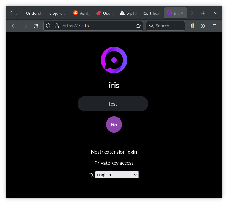
When opening the website the first time one is greeted with a login page.
The login page asks you for your display name and here I just entered test for demonstration purposes.
When clicking Go, the web application creates a public and private key pair.
The next page shows you a selection of popular accounts which you can choose to add to your feed by pressing one or more of the Follow buttons.
The next page lets you choose a unique user name for the iris.to website.
If you for example choose testit, you get a human-readable Nostr address (a so called NIP-05 name) called testit@iris.to.
Of course you can always choose to get a new Nostr identity from another website.
If you have a private homepage with the URL https://myhomepage.org, you can even create your own Nostr identity testit@myhomepage.org.
More about this later.
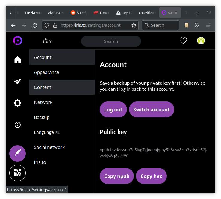
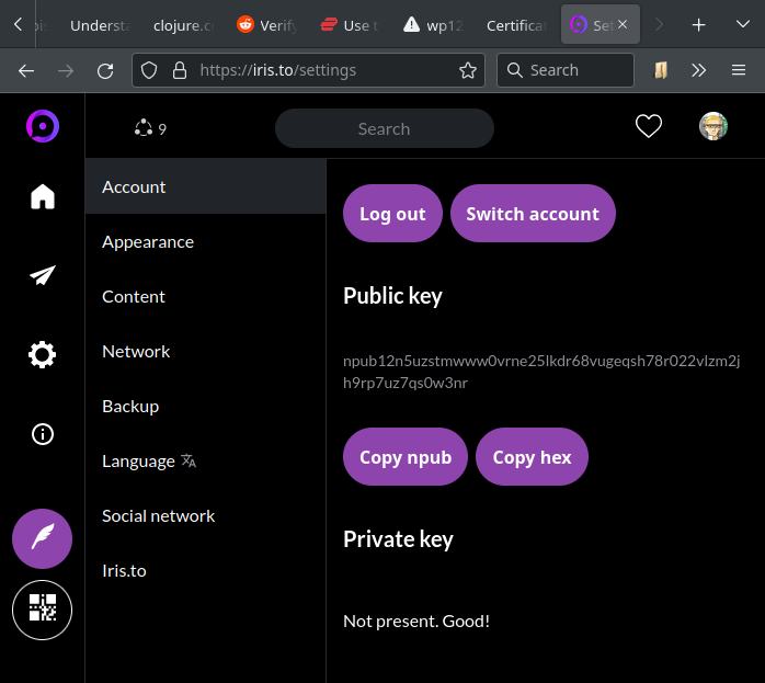
If you navigate to the account page, you will see your public key, which is a long string starting with npub....
If you scroll down, you will see a button to copy your private key to the clipboard.
The secret key is a long string starting with nsec....
Now is a good time to store this private key securely, otherwise you will permanently loose access to this account.
If you loose your secret key, your only option is to start over with a new account.
You will need this key if you get a new PC or if you want to use Nostr on another device or client.
Depending on your browser’s privacy settings, you might need the key next time you restart the browser.
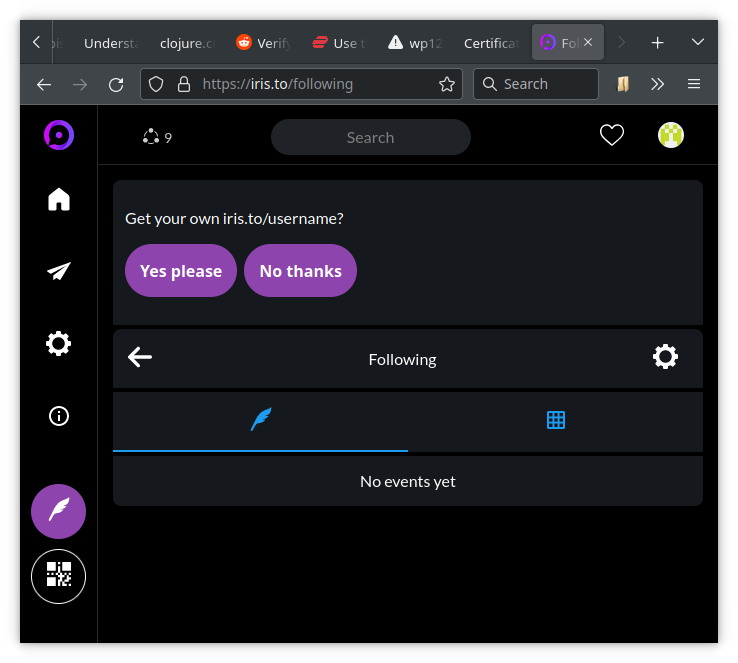
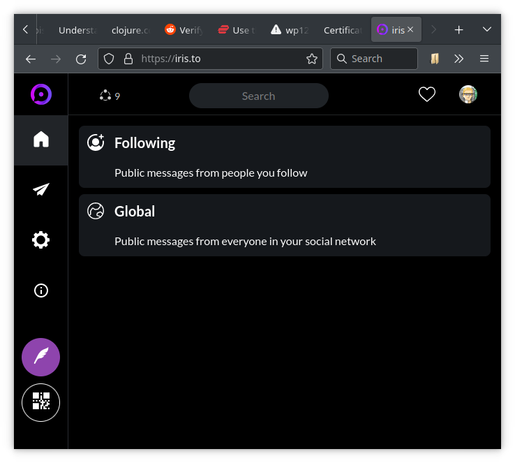
When clicking on the home icon, one gets presented with two options:
Following: show messages from accounts you follow
Global: show messages from your extended social network
When clicking on Following, you will see a real-time feed from accounts you follow.
Also the top of the page shows you a button to copy a link to your public feed to the clipboard.
If you haven’t chosen a human-readable Nostr identity, the link will be something like https://iris.to/npub....
If you have chosen the name testit, your public link will be https://iris.to/testit.
If you are using your private homepage to create a Nostr identity, you can also use https://iris.to/testit@myhomepage.org as public link.
BTW, if you are looking for new type of content, you can search using the hash-tag #grownostr.
BTW, if you want to send/receive zaps (small tips using Bitcoin Lightning), I can recommend the Alby web wallet.
Advanced Users
This section is for advanced users only and is purely optional.
Nostr extension login (somewhat advanced)
You might have noticed that in my screenshot the login page has a clickable Nostr extension login link which makes login easier.
This is because I am using the Firefox extension nos2x-fox which manages logging in without revealing the private key to the web application.
In my case if I go to the account page, there is no option to copy the private key because the web application does not know it.
In a similar fashion, desktop clients can post messages to relay servers without revealing the private key.
Nostr address using private homepage (more advanced)
Note that the account page also has a Copy hex button which lets you copy your public key in hexadecimal form.
In order to use your homepage to give you a check mark verifying the Nostr address testit@myhomepage.org, you need to place a JSON file at https://myhomepage.org/.well-known/nostr.json with the following content:
{"names":{"testit":"<your public hex key>"}}
Also you need to enable CORS.
You can do this by adding a .htaccess file with the following content in the .well-known folder:
Header set Access-Control-Allow-Origin "*"
Header set Access-Control-Allow-Methods "GET"
Header set Access-Control-Allow-Headers "Content-Type, Authorization"
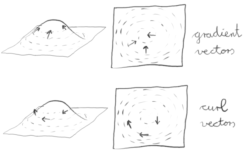
In two dimensions curl noise is fairly easy to understand and implement.
For a thorough description of 2D curl noise see Keith Peters’ article “Curl noise, demystified”.
Basically one starts with a potential field such as multiple octaves of Worley noise.
One then extracts the 2D gradient vectors and rotates them by 90°.
To generate curl vectors for a spherical surface one can use 3D Worley noise and sample the gradients on the surface of the sphere.
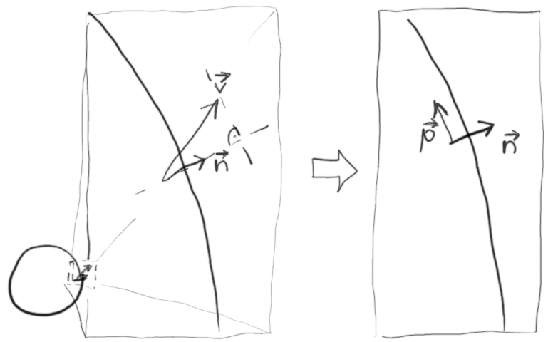
The gradient vectors then need to be projected onto the sphere.
This can be achieved by projecting the gradient vector onto the local normal vector of the sphere using vector projection.
By subtracting the projected vector from the gradient vector one obtains the tangential component of the gradient vector.
The resulting vector p needs to be rotated around the normal n by 90°.
This can be achieved by rotating the vector p into a TBN system, rotating by 90° around N and then transforming back.
The GLSL functions for the rotation (without OpenGL tests) are shown below:
#version 410 core
vec3orthogonal_vector(vec3n){vec3b;if(abs(n.x)<=abs(n.y)){if(abs(n.x)<=abs(n.z))b=vec3(1,0,0);elseb=vec3(0,0,1);}else{if(abs(n.y)<=abs(n.z))b=vec3(0,1,0);elseb=vec3(0,0,1);};returnnormalize(cross(n,b));}mat3oriented_matrix(vec3n){vec3o1=orthogonal_vector(n);vec3o2=cross(n,o1);returntranspose(mat3(n,o1,o2));}// note that axis needs to be a unit vectorvec3rotate_vector(vec3axis,vec3v,floatcos_angle,floatsin_angle){mat3orientation=oriented_matrix(axis);vec3oriented=orientation*v;mat2rotation=mat2(cos_angle,sin_angle,-sin_angle,cos_angle);vec3rotated=vec3(oriented.x,rotation*oriented.yz);returntranspose(orientation)*rotated;}
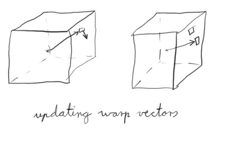
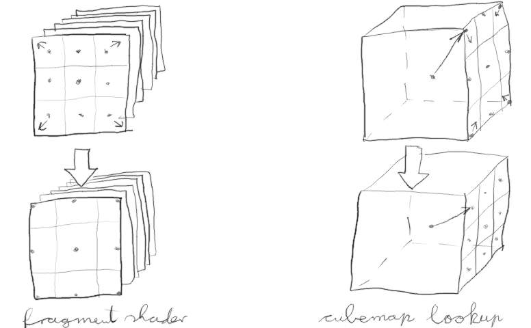
In OpenGL one can create a cubemap where each pixel on each surface contains a 3D warp vector.
Using a fragment shader the cubemap is initialised to be an identity transform for unit vectors.
A second fragment shader is used to initialise a cubemap with the curl vectors which are tangential to the sphere.
A third fragment shader is called multiple times to renormalize and increment the identity transform to become a warp field.
A final fragment shader uses the cubemap warp field to perform lookups in a 3D Worley noise field to generate a cubemap of the global cloud cover.
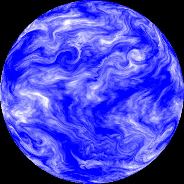
If one uses octaves of Worley noise one obtains vortices rotating in one direction.
To obtain prevailing winds and vortices with different direction of rotation depending on the latitude one can use the function (1+sin(2.5*latitude))/2 to mix positive and negative Worley noise.
Below is a result obtained using the method described in this article.
Another detail I forgot to mention is that the fragment shaders and the cubemap texture lookups use modified vectors to avoid performing lookups in the texture clamping regions which would lead to seams in the cloud cover.
I.e. when converting fragment coordinates, one increases the range of the index by half a pixel on both ends:
vec2x=(gl_FragCoord.xy-0.5)/(size-1);
Furthermore when performing lookups, two coordinates of the lookup vector are scaled down by half a pixel: